


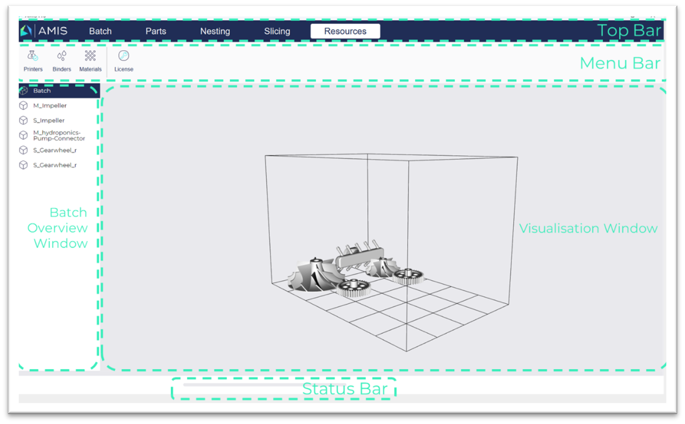
6. Features and Functionality
6.1 Batch creation
Starting the workflow typically takes off with either starting a new batch or continuing the work on an existing batch.
- Prior to starting a new batch, the applicable printer can be chosen. The corresponding build box dimensions will be loaded and displayed in the 3D-view area. Note that the printer selection can be altered at a later stage - although this may impact the viability of the print (e.g. if the printer dimensions are smaller and consequently not all parts fit the build box.)
-
Alternatively, the user can select to continue working on an existing batch.
-
Adding parts
the user can add parts into the printers' Build box.
- while adding the part(s), check for errors in the file(s) and correct the errors if possible;
- optimizing the parts' positioning (for 3D-printing);
- Apply binder-, material-, and part-optimization algorithms;
- Optimally nest the parts into the Build box;
- (preview) Slicing of the build box;
- Send the build box instructions to the printer (i.e. slice the parts, 3D-RIP the parts, etc).
Currently, the following file formats are supported:
6.2 Part and Batch Preparation
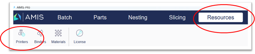
In order to add parts to a batch, move to the second tab in the header and click the “Import” icon:
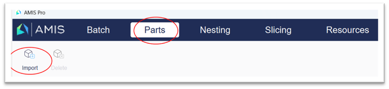
A file explorer window pops up, allowing you to navigate to the location where your part files are stored and select the appropriate part. When you double-click on a part, it will be imported into the build box (batch). Repeat this action to import multiple parts.
Note: at this point, AMIS Pro allows for the import of .STL files only.
Note: at this point, only one part can be selected at a time.
Parts that are imported, also appear in the Batch overview window in AMIS (in this case, 5 parts have been added into the batch):
Note: parts are added in the middle of the build box. This implies that parts may be (partially) “inside” other parts and therefore not (entirely) visible in this stage. The Batch overview window allows you to keep an overview on the parts already imported. Upon nesting (see below), all parts will become arranged next to each other.
Once you have added all parts for the batch, you can proceed to the next step: nesting.
Note: it is possible to add additional parts after nesting and/or after slicing.
6.3 Positioning, Scaling, and Rotation of Parts
(NA)
Positioning
Scaling
Rotating
Locking position, scale or rotation
6.4 Settings for Binder Use and Layer Height
6.5 Shell-Grid-Core
1. definition
Shell-Grid-Core or SGC is a functionality allowing the user to define the binder deposition on the outer hull (Shell) or inside (Core) of a part. It similarly allows for constructing an inner grid structure (Grid) that enhances strength of the part.
2. functionality
- Shell: The "Shell" is a definable layer forming the outer surface of a part. Its thickness as well as the binder saturation herein are adjustable in the SGC settings tab. The purpose of the shell is to provide sufficient strength to the part as to be able to remove the part from the build box, place it into the curing oven and sinter the part without any damages. A thicker shell obviously leads to stronger parts, but also implies longer de-binding and/or sintering cycles, as well as higher binder consumption. As for defining the shell thickness, the user will have to make an estimated guess based upon experience, binder and material qualities and the part shape.
-
Grid: the grid is an optional, adaptable inner structure inside the part to be printed. The Grid function allows users to define and apply a grid-shaped 3-dimensional structure. In general, a thicker grid and a
The grid structure is adaptable as follows:
-
Core: